Voice over Internet Protocol (VoIP) is an important alternative to circuit switched telephony. This page shows some of the infrastructure associated with a VoIP private branch exchange (PBX) at Champlain College.
Hardware Architecture
What does a VoIP system physically look like? When compared to a circuit switched system a VoIP user must be very close to the edge of the network. In other words, a VoIP user must have lots of bandwidth available. It's just not practical to have a VoIP user sitting at the end of a 10 mile long local loop!
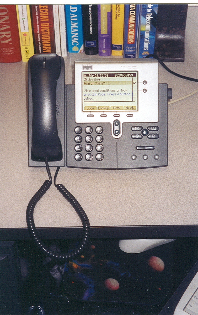
The user device is very different from POTS technology. A typical VoIP phone looks more like a computer than an old Bell System Model 2500 POTS phone. At Champlain we use a Cisco system and each of these phones uses a variation on the XML web language. Here are two photos of a Cisco VoIP phone.
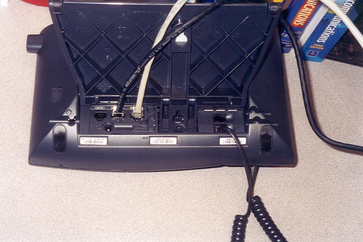
The connection to the network is via a high speed Ethernet data connection located on the bottom. It's a conventional RJ-45 plug with some CAT-5 cabling. You'll see that there are two connections in the photo,. One connection goes to the network and the other to a PC. In this case the phone is acting like a network hub for a PC. This arrangement should convince you that in the VoIP world data packets and voice packets are just collections of bits to be moved over a common network.
VoIP CPE
The first big difference from a POTS phone is the screen. Depending on what's being done the screen will show called numbers, caller ID information, voice messages stored, etc. Web information can be displayed as well as telephony related parameters, the weather, or the lunch menu at the cafeteria. Obviously the screen is going to change and this ability to alter it gives a high degree of flexibility. Contrast this to a conventional PBX phone with fixed key functions and no display.
There are hard keys that do one specific function. For example, the number keys, the voice mail key, the hold button, etc. do only one thing. You'll also see "soft" keys whose functions change with the task. The screen will label the soft keys according to its programming.
If you think about it you'll realize that this little computer-phone needs power to operate. Conventional POTS technology receives power over the local loop from a CO battery and VoIP phones do roughly the same thing. However, there's no dedicated local loop but instead there's a connection to a shared Ethernet.
The original IEEE 802.3 Ethernet specification doesn't provide for DC power over data circuits. To make VoIP possible vendors such as Cisco developed an interim and nonstandard solution to perform power over Ethernet (PoE). These vendor solutions are moving toward an agreed upon international standard and this effort is at the heart of the IEEE 802.3af standard. However, many vendors have not agreed on wiring, connector, and voltage standards. Therefore, integrating POE devices from different vendors can be problematic.
Meanwhile, Down In The Basement.....
If we were to trace the wiring from our Cisco phone we'd find it ends up at a router in a wiring closet down the hall or in the basement. Aside from the POE capability it is pretty much a conventional data router. Here's are some photos:
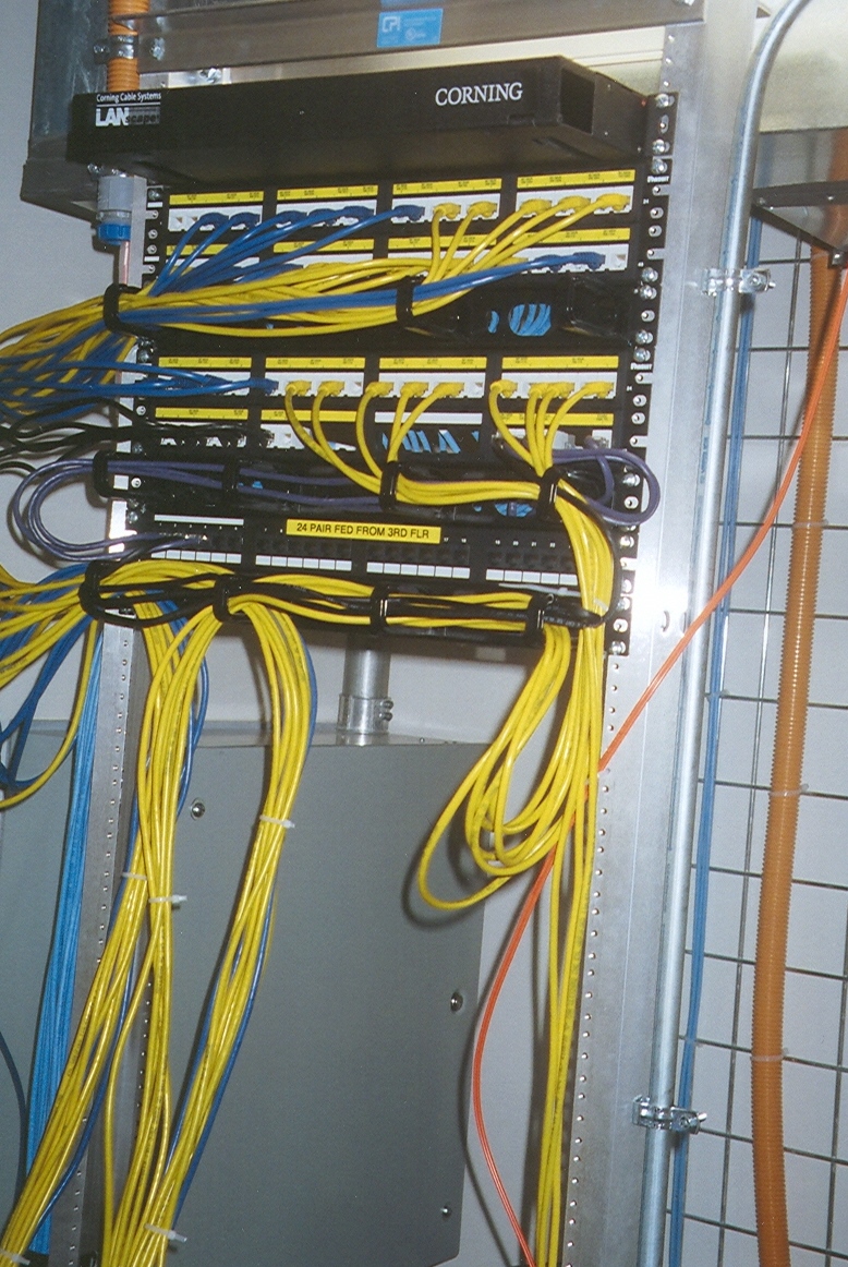
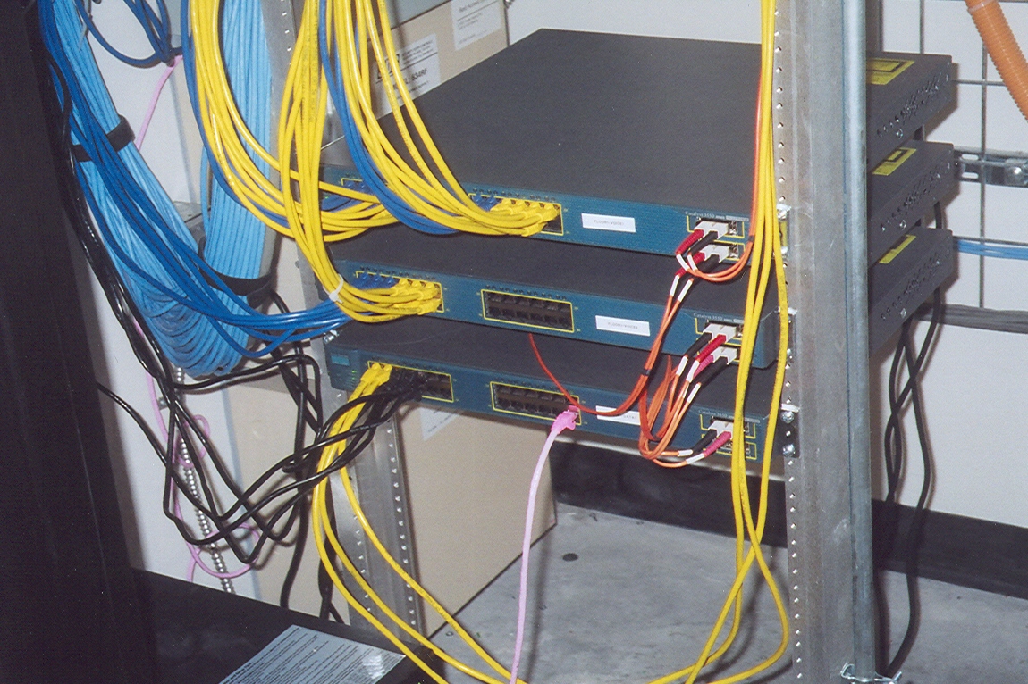
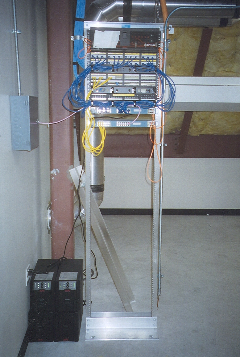
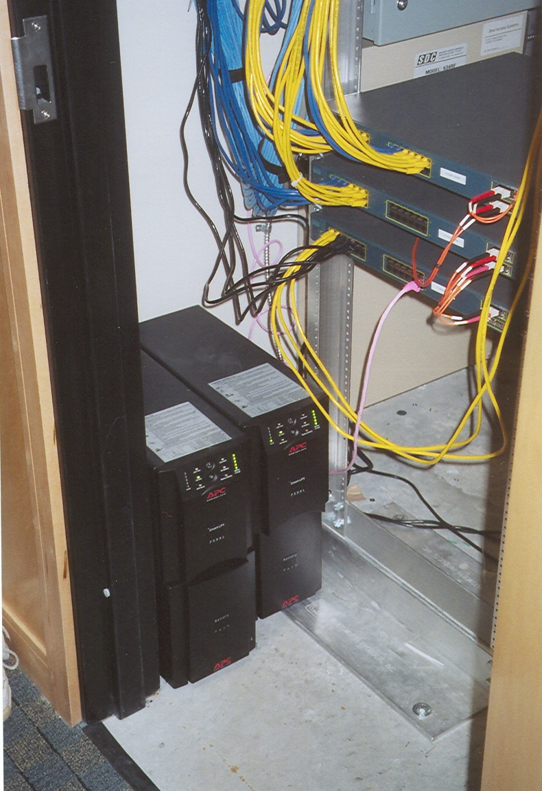
The router is going to connect the building's telephones to the campus backbone. In this photo the backbone connections are made via fiber optic cables and these are the small orange cables on the right side of the routers.
You'll note in this photo that there are uninterruptible power supplies that are powering the routers. These supplies are like the CO battery banks and they ensure that the routers will have power---and the phones will work---if there's a power outage. However, unlike a CO battery bank these supplies deliver standard 120 V AC power to the routers.
Central Control
Eventually the data backbone is going to end up at a central point where the voice network is managed. You can think of this as a VoIP PBX system since it's here that you'll find the boundary between the local data network and the PSTN and/or Internet. Here's an annotated photo of the VoIP PBX rack.
Let's look at what each piece of gear does. Starting from the top:
Not in this picture is the gateway that handles the interface with the PSTN.