Telephone Central Office
This is a virtual tour of the telephone central office (CO). Click on any of these thumbnail images to see a larger version of the picture.
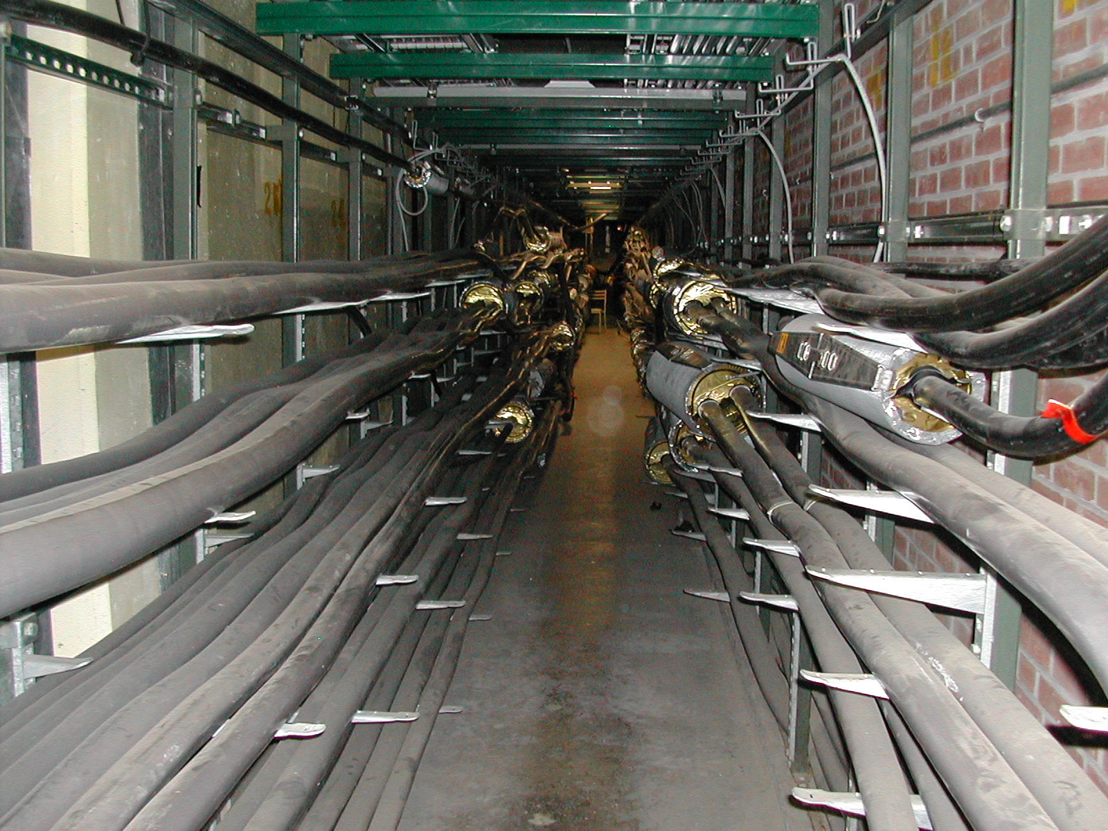
Cable Vault
Local loop pairs, T-carriers and fiber optic cables all converge in the cable vault in the basement of the central office. This area is usually below ground and it is considered to be a hazardous area because of the potential for accumulating sewer gas (methane). It is standard practice for personnel to test for gas before entering the vault. Cables leave the vault and then travel to the main distribution frame upstairs in the CO.


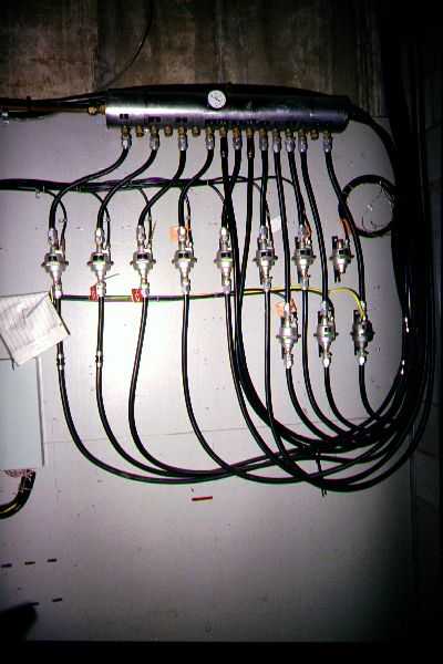
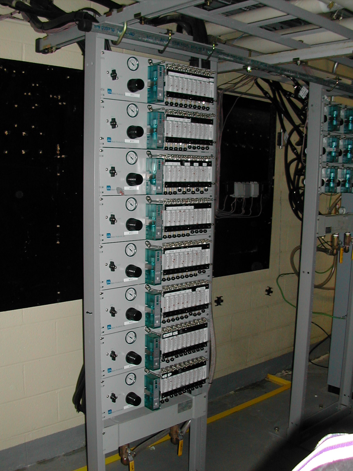
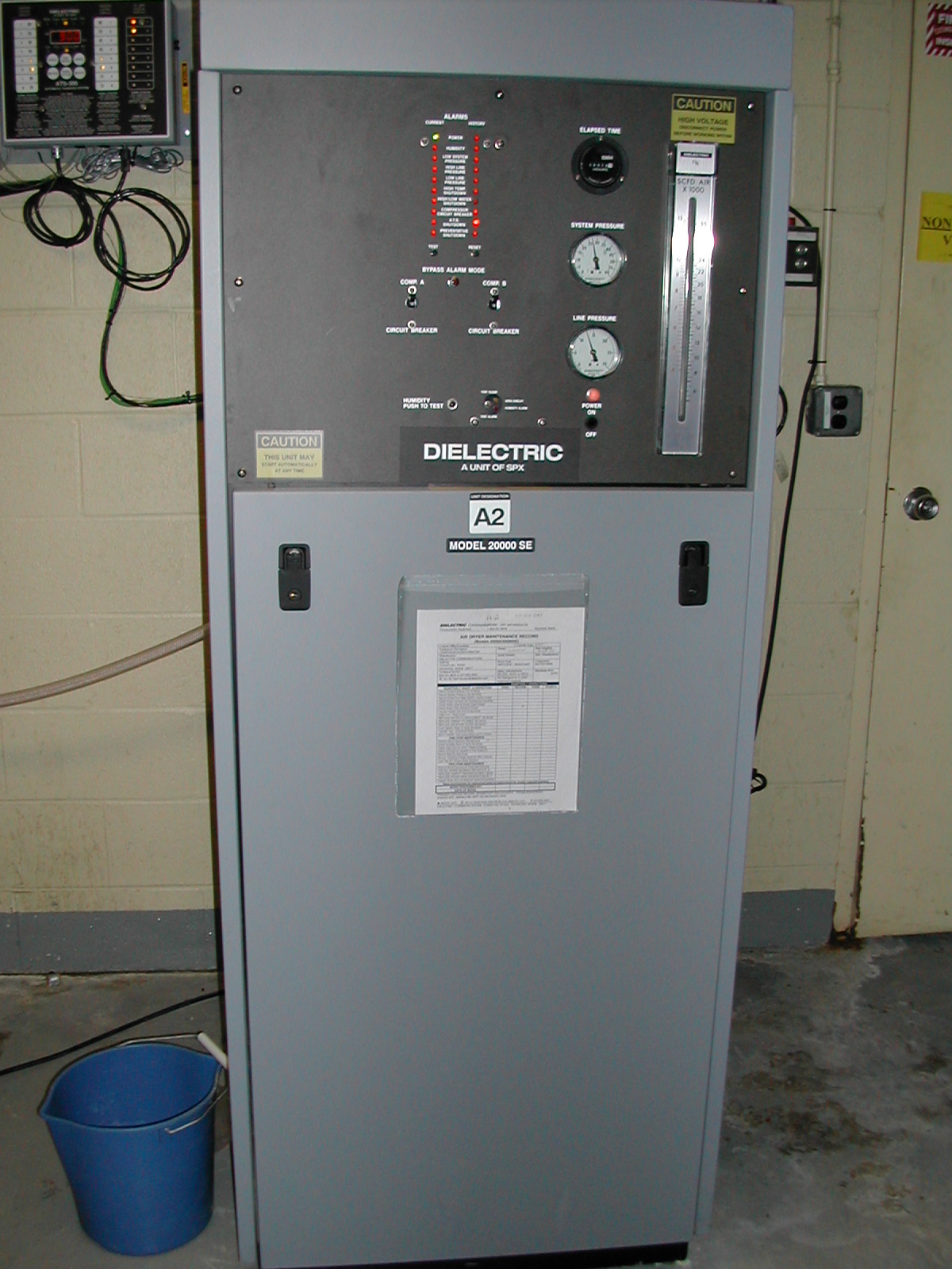
Some cables are pressurized in order to prevent moisture from penetrating the cables. First, there's an image of a gas manifold that controls and delivers the air to the cables. Second, there's a view of the manifold attachments to the cables themselves. The two units on the right are the air dryer and pressure control. .
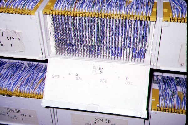
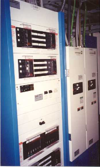
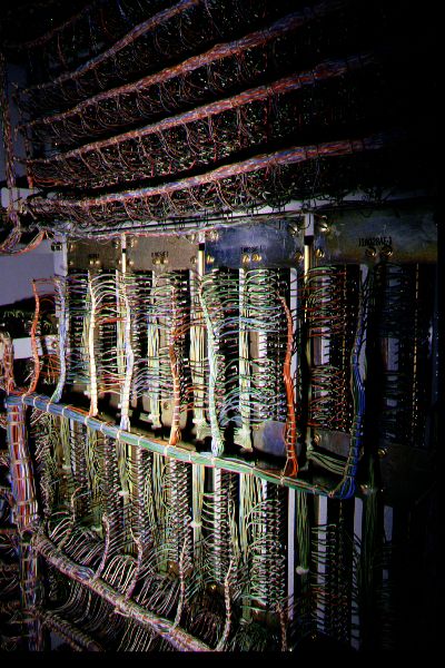
Main Distribution Frame
The main distribution frame (MDF) is a junction of local loop pairs and line card connections. Local loop pairs terminate on the vertical side. The red protection blocks are for special circuits such as T-carriers or ISDN circuits. Green blocks are usually reserved for CLEC loops. .

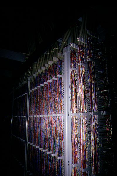
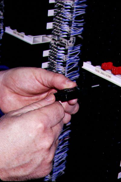

The cables that go to the CO switch terminate on the other (horizontal) side. There are jumpers that cross connect these two sides. Protection blocks are found on the local loop side. These protection blocks prevent excessive voltage from damaging the CO switch.


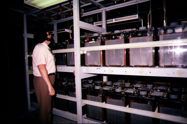
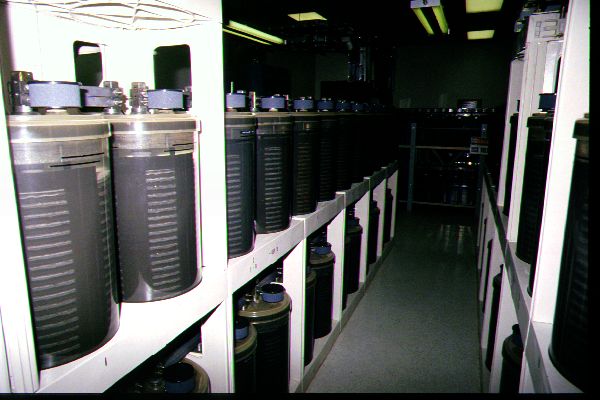
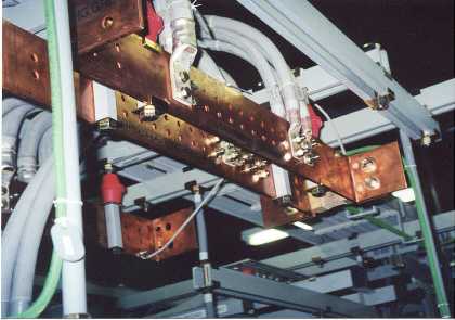
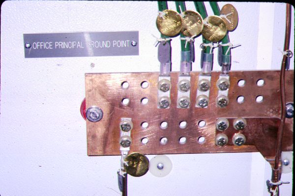
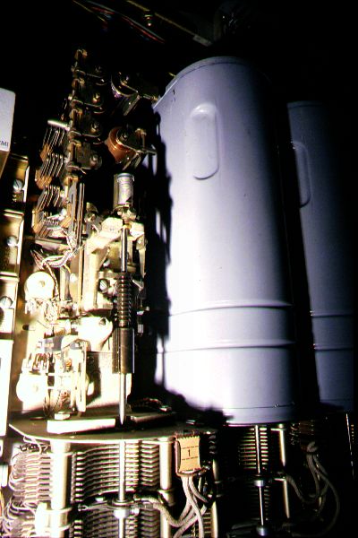
Power Supply
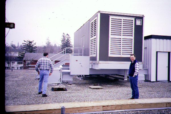
The CO switch is run by a combination of AC powered rectifiers and batteries. The batteries are rated at 48 volts DC and the rectifiers supply 52 volts DC. The rectifiers keep the batteries charged and they power the CO equipment while the electric company power flows. If the power fails then the batteries which are "floating" seamlessly take over the load. The CO switch and other equipment don't notice the difference and everything keeps operating. If the power comes back on in a few minutes the rectifiers take over again. If, however, there is a long outage then a generator starts and keeps current flowing to the rectifiers. The generator shown here is on the roof of a CO and supplies about 750 kva. Most central offices have a large fuel tank to keep the generator running for days. This power supply system keeps the switch running reliably throughout many adverse conditions.
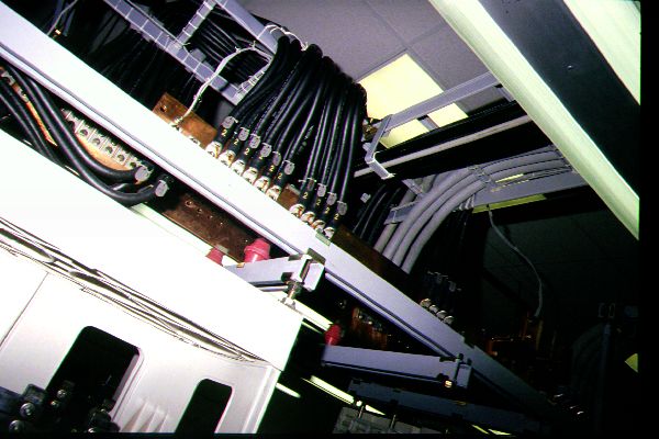
The CO equipment draws a lot of current and all of the wires and conductors are very large.

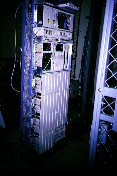
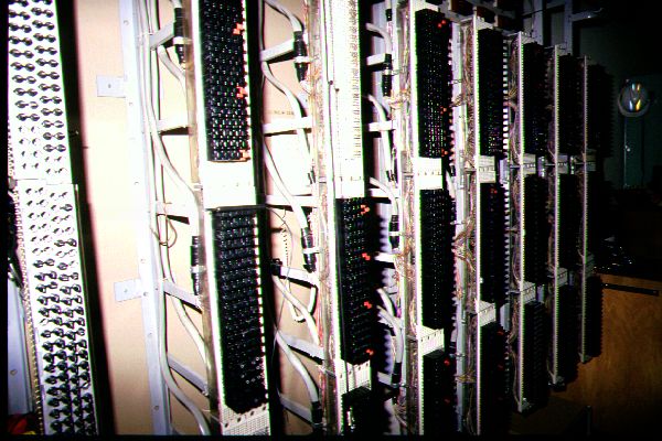
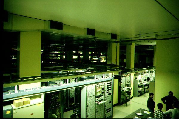
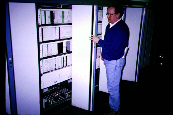
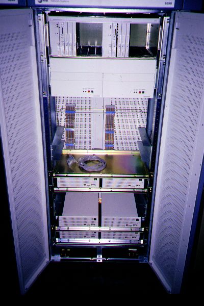
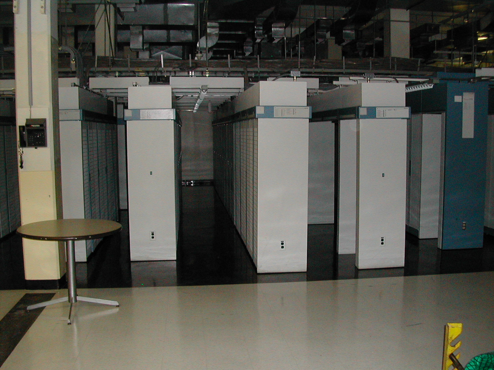
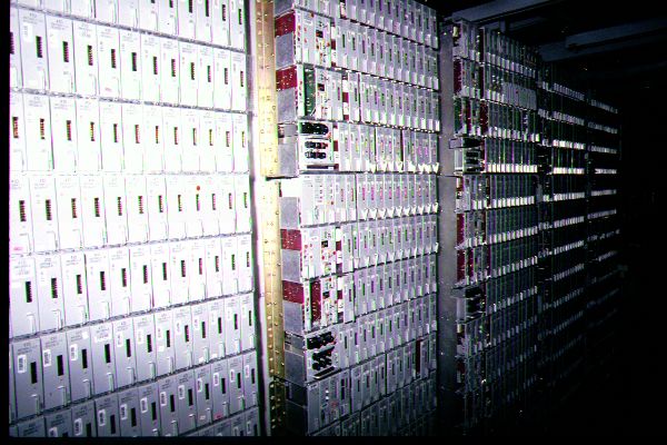
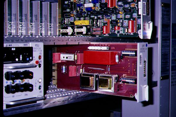
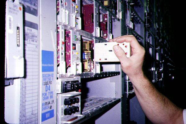
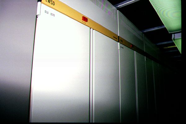
Electronic Switches
These next few pictures show electronic central office switches. Most of these are the #5ESS from Lucent but there are some other types represented too. You'll notice that these switches look very much like large computers....which they are! Printed circuit cards can be replaced and added very easily and this feature makes expansion and maintenance very easy. Technicians don't have to solder and unsolder components. Instead they slide out a card and replace it with a new one.

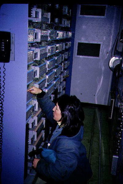

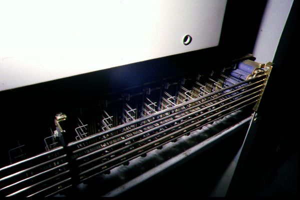
Electromechanical Switches
There is a lot of reference in telephone texts to switching technology that is old and not used very much anymore. Here are a few views of some electromechanical switching equipment. This technology was developed before electronic computers were available and there are lots of moving parts. That's where the "mechanical" in electromechanical comes from. For more information on electromechanical switching see the images from the New England Museum of Telephony. They're on the root Images page.


The Smithsonian Institution in Washington has an exhibition on communications technology and they've included a "Bell System Switching Station" in the exhibit. Now, you'll never see a real central office switch that looked like this! For example, it's going to be much bigger than this little exhibit and it's not going to appear in a glass store front. If you ever get to Washington check it out: the equipment inside is a small section of a crossbar switch. You can get a good idea of the complexity of the mechanical components from just this small segment.

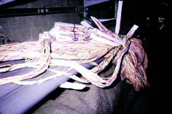
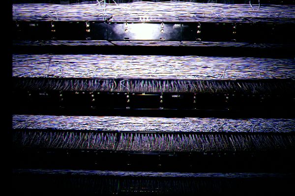
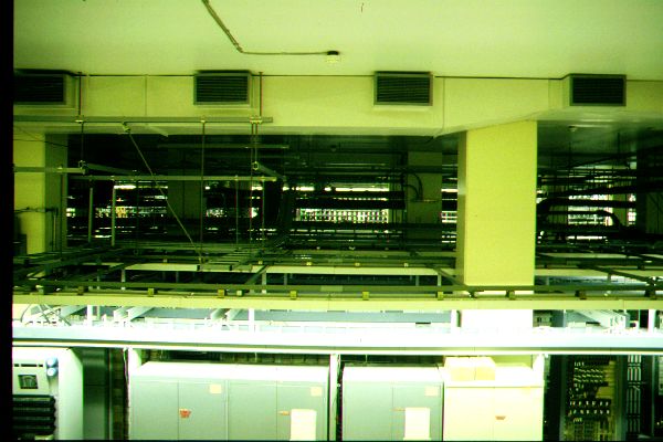
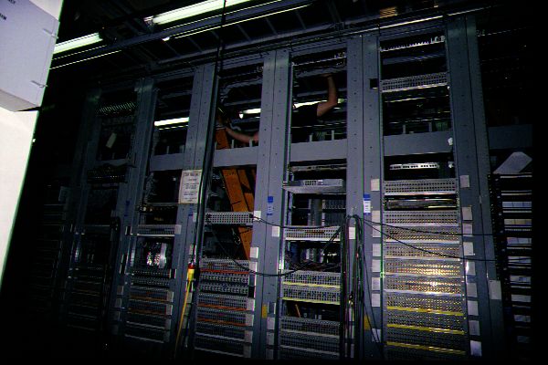
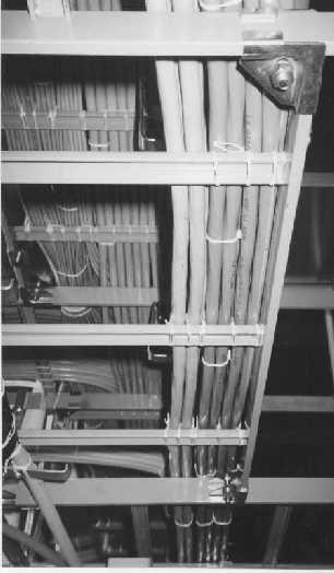
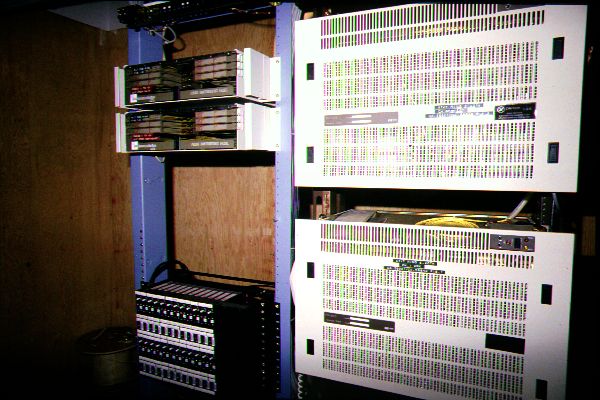
Media and T-carriers
There is a lot of copper wire and fiber optical cable in any CO. Standard twisted pair copper wire is used to support local loops and lower speed T-carriers. Optical fibers are used to carry many calls in a very small physical package and are used for connections to other central offices, Competitive local exchange carriers (CLECS), and interexchange carriers (IXCS). The highest speed trunks are supported by fiber optic cable and are based on synchronous optical network (SONET) protocols. Lower speed options include T-carriers. The basic T-carrier is the T-1 and it can carry 23 or 24 voice conversations. It operates at 1.544 Mbps. The term "multiplexer" refers to any equipment which aggregates several conversations onto a single wire or fiber optic cable.


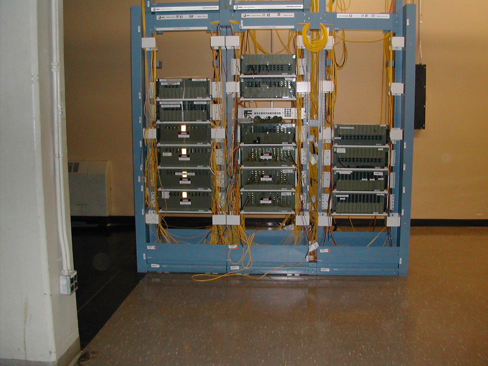
Cage
Competitive local exchange carriers (CLEC) and interexchange carriers (IXC) often have a presence in a competitor's central office. This is called a "POP" for point of presence. These carriers have clearly defined physical boundaries for their operations and their equipment is usually located in a wire cage. The "outsider's" equipment is inside the cage, the carrier's equipment is outside of the cage.