These are images associated with personal computers and local area networks. Yeah, they're all pretty dated so consider this a history page rather than a shopping page. Click on any of these images to see a larger version of the picture.
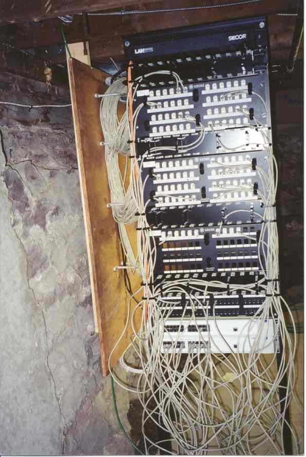
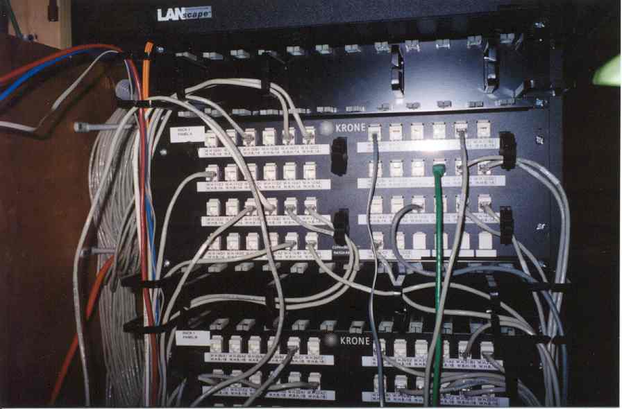
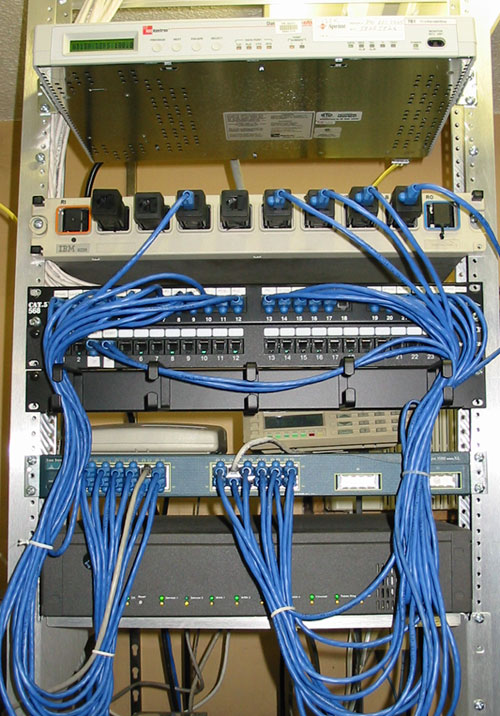
This first collection is from the Champlain College West Hall basement. This is an example of a typical building wiring scheme. You might find this kind of configuration tucked away in a basement or in a wiring closet for a small- or medium-sized installation.
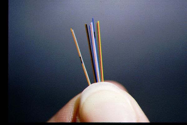
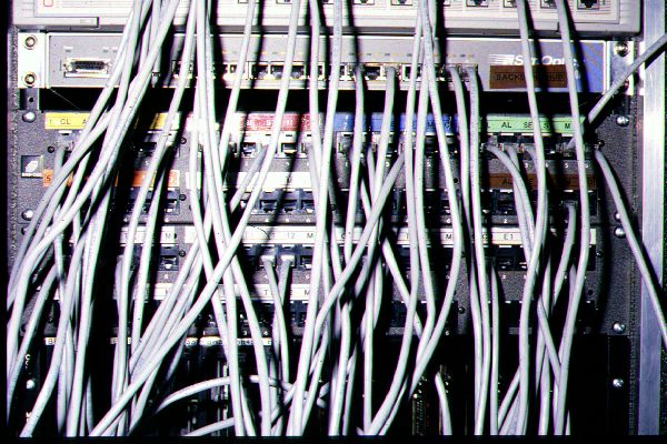
West Hall connects to the campus network by some fiber optic cables. They are the orange cables on the right of the hubs. Note that each hub has two fiber optic cables, one for transmitted data and one for received data.
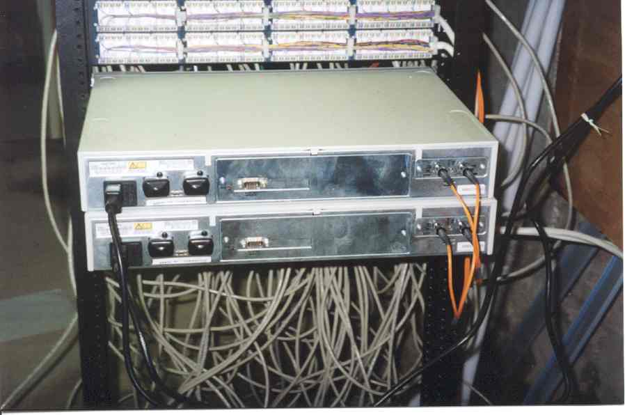
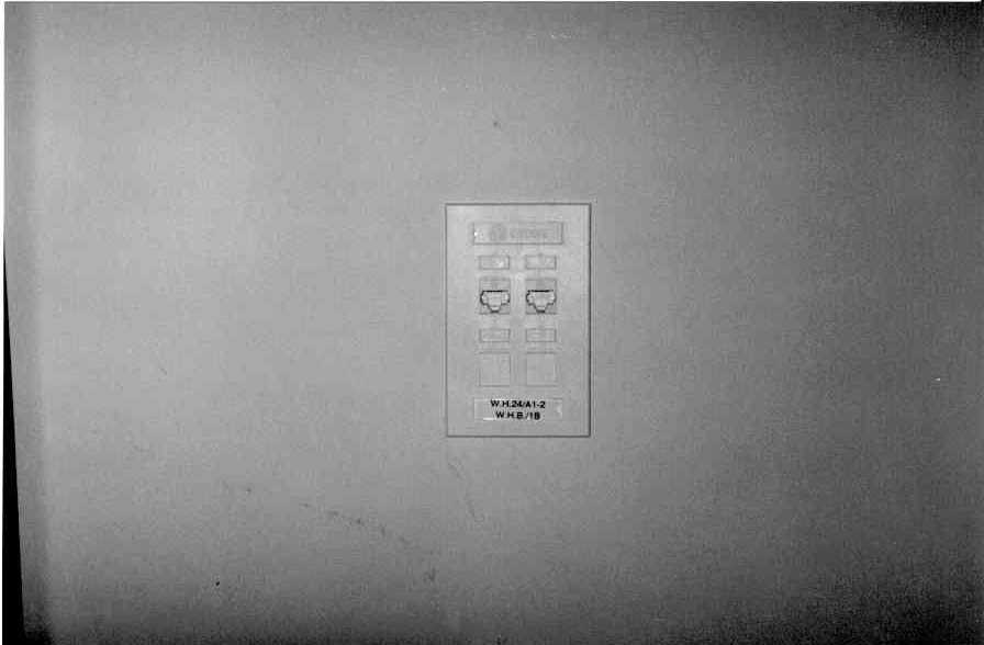
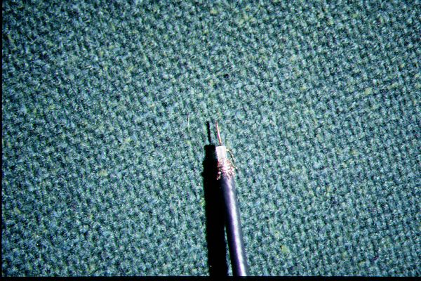
Each office in West Hall as a RJ-45 outlet plate. A PC with a NIC card can plug into one of these jacks. The other end of the jack terminates in a patch panel in the basement. A patch cable is used to connect a port on the hub to a jack in an office. For example, note the path of the green wire between a jack on the hub at the bottom and an office jack at the top. There's also a close-up of a RJ-45 patch cable.
![]()
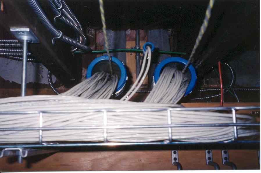
Here's an image of the cables from the wall outlets entering the basement. They are leaving the conduits with the blue edges. Note the trays that hold the cables. There are fish lines in both conduits and these will be used to pull new cables in the event more wires need to be added to the conduit. The fish lines come out of the top of the conduits and are temporarily tied on the black pipe.


So much for West Hall. Here are a couple of views of specially wires and cable.
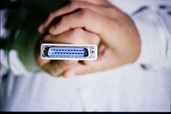
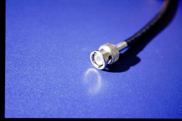
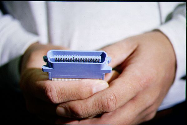
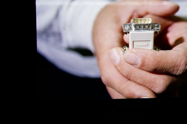
Here are some views of connectors commonly found in PC and LAN work. From left to right: RS-232C/DB-25, V.35, BNC, Centronics, and RS-232/DB-9.

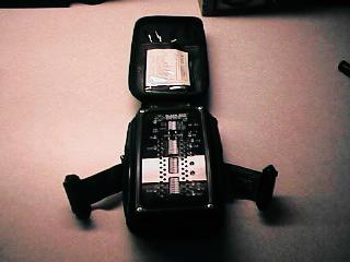
Here is a hardware protocol analyzer (they can be built into PCs) and a RS-232C breakout box.

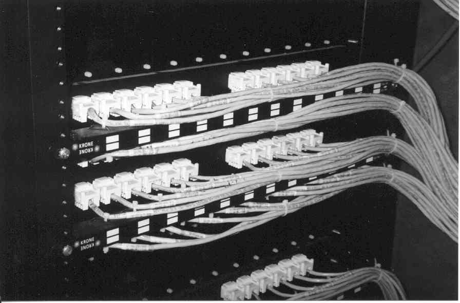
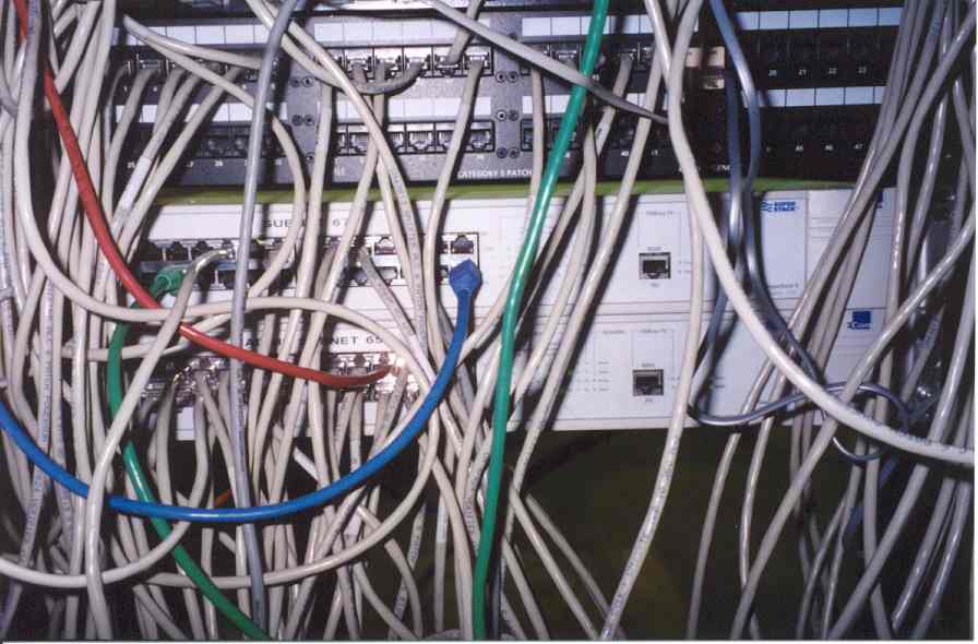
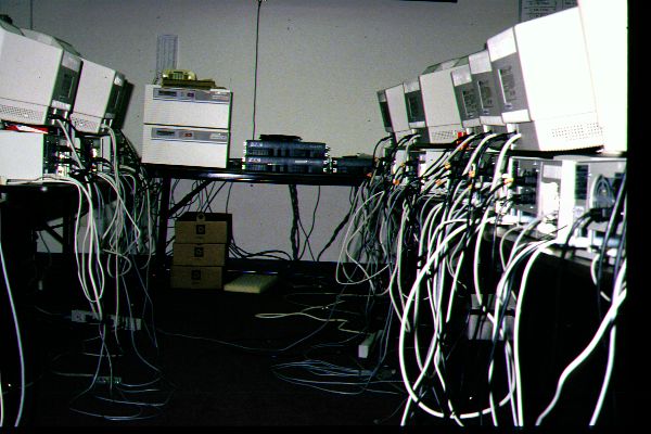
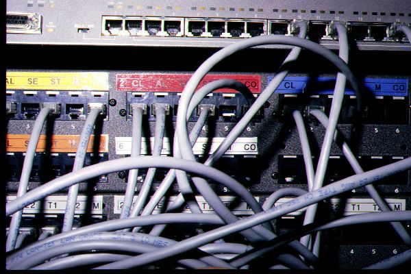
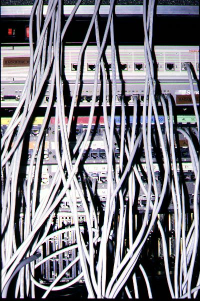
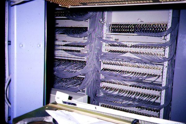
Here's some typical wiring. You may get some ideas about dressing up your own installation. There are several references to wiring and cable management equipment companies in the Useful Links page of this web site.
In these examples most of these connectors are RJ-45 which terminate CAT-5 wires. The last image is a classic example of "fur ball" wiring. It's an example of how not to do wiring!

When you connect your LAN to a digital WAN (e.g., a T-1) you'll be using a router or bridge. However, between the router and the telco connection there's a device called a channel service unit/digital service unit or a CSU/DSU. To make a long story short this device takes the 4-wire digital signal from the telco and converts it into a format that the router or bridge can use. It provides a compatible physical connection to the router such as V.35 and a connection to the telco such as an RJ-45 or RJ-48. Here's an annotated view of a CSU/DSU.
.