Some Notes on Loading Coils
Copyright © 2005 Dave Whitmore
The purpose and nature of loading coils is often misunderstood. Here's a little background and an explanation of what loading coils are, what they are not, and how they work.
Normally the local loop between your house and the telco central office switch is fairly short. Generally the length is 3 miles or less. At these distances the twisted pair local loop wires are basically just wires. There's nothing special about them--they're just conducting the voice and DC signals between the CO switch and the customer premises POTS equipment.
On local loops over 3 miles long nasty things happen to the voice signal. At these longer distances the effect of the mutual capacitance of the two twisted wires themselves becomes significant. Remember that a capacitor consists of two conductors separated by an insulator (the dielectric). The two insulated twisted wires in the local loop meet this definition of a capacitor.
The capacitance of the wires is about .083 microfarad per mile which isn't significant for short local loops. However, the capacitance of the wires does affect the frequency response of the local loop over long distances. Here's why. Remember that the bandwidth of the PSTN is between about 300 Hz. and 3,300 Hz. This is the band in which most human speech occurs. Below are two graphs, one showing the normal, expected frequency of the local loop and the other showing the effects of a long, unloaded local loop. (BTW, these graphs are intended to be only approximations.)
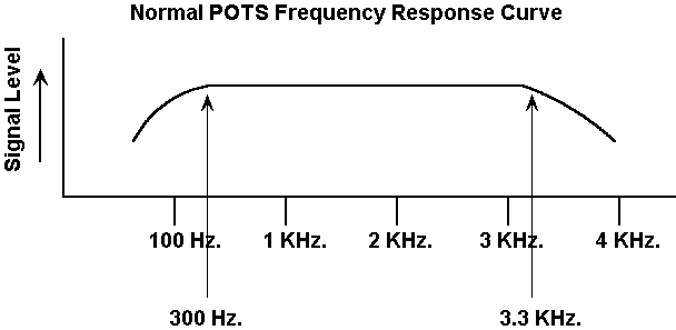
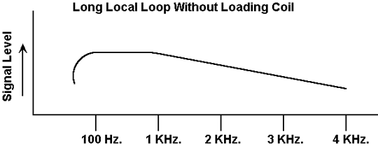
So you can see the problem. The higher end of the voice band is tailing off and the high frequency response of the local loop is adversely affected. This makes speech sound unnatural.
The Solution
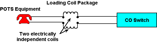
The cure is pretty simple and was discovered by two different inventors in 1899, one of whom worked for the Bell System. Loading coils are placed in series with both the tip and ring lines of the local loop. These coils are just a coil of wire. No more, no less. The loading coil is a passive device and does not receive any external power. It is neither an amplifier nor a repeater. It's just a coil. Here is a photograph of a loading coil:
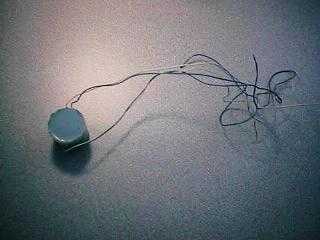
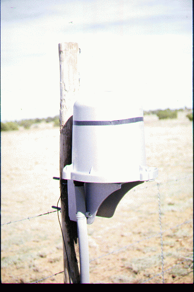
In this photograph there are actually two coils in one physical package. This configuration was chosen because loading coils are always installed in pairs. In the field loading coils are often put into sealed containers called "pots". Here's what one looks like:
Here's a schematic diagram showing the coil installed in a POTS local loop.
Results
The inclusion of the coils makes speech sound natural by "jacking up" the upper end of the frequency response curve. Now it would be nice to say that the loading coils fix everything and that we're back to the ideal frequency response curve for a POTS line that we saw above. However, the coils don't fix everything and in fact introduce a side effect..
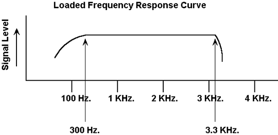
The loading coils make the voice band flatter but the high frequency end of the band is sharply attenuated after 3,300 Hz. While this doesn't affect voice reception it does affect modem performance. Modems "cheat" by using frequencies above the normal voice band and the sharp attenuation caused by the loading coil cuts off a range of frequencies used by modems. The net result is that loaded local loops do not perform very well with modems. Here's what the loaded frequency response curve looks like. Note the relatively sharp drop off on the right when compared to the "normal" frequency response curve.
Some Theory
You can safely skip this section if you don't want to know about the electrical engineering behind this phenomenon.
A loaded local loop is basically a low pass filter. Here is an abstract view of a low pass filter.
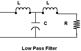
In this diagram L stands for an inductor (loading coils) and C stands for capacitance. In this case C is the mutual capacitance of the local loop wires. The critical frequency of this circuit is the point below which frequencies pass with relatively little attenuation. Above this frequency the attenuation increases sharply. Here's the formula:

An outside plant engineer will adjust the inductance of the loading coils while considering the length and gauge of the wire. The latter two factors affect the capacitance in the equation. The target frequency for the critical frequency is--surprise!--3,300 Hz. It's the sharp drop off at 3,300 Hz. that poses problems for modems. Local loops can be loaded to push the critical frequency further up but it's not generally done for POTS lines. Now to some practical concerns.
Spacing and Other Details
There are three basic variables that are considered in designing extended local loops: (1) Inductance of the loading coils, (2) Spacing of the coils, and (3) Gauge of the wire.
1. Loading coils come in two inductances, 44 millihenries (mh) and 88 mh.
2. Several different spacing arrangements are possible. The Bell System standardized on the following schemes. Each scheme is designated by a letter:
|
Letter
|
Coil
Spacing (feet)
|
|
A
|
700
|
|
B
|
3000
|
|
C
|
929
|
|
D
|
4500
|
|
E
|
5575
|
|
F
|
2787
|
|
H
|
6000
|
|
X
|
680
|
|
Y
|
2130
|
3. Long local loops often include heavier gauge wire and 19 or 22 gauge wire is often used.
An outside plant engineer might describe a particular arrangement as 19H44. The first number is the wire gauge (19), the letter is the spacing arrangement from the above table (6000 feet), and the last number is the inductance in millihenries (44 mh).
Each loading coil as a DC resistance of about 5.5 ohms which could affect the local loop current when going off hook.
References
Telecommunications Transmission Engineering. Volume 1: Principles. Bell Telephone Laboratories, 1977
Engineering and Operations in the Bell System. Bell Telephone Laboratories, 1977.
Telecommunication System Engineering. Third Edition. Roger L. Freeman, Wiley Interscience, 1996